

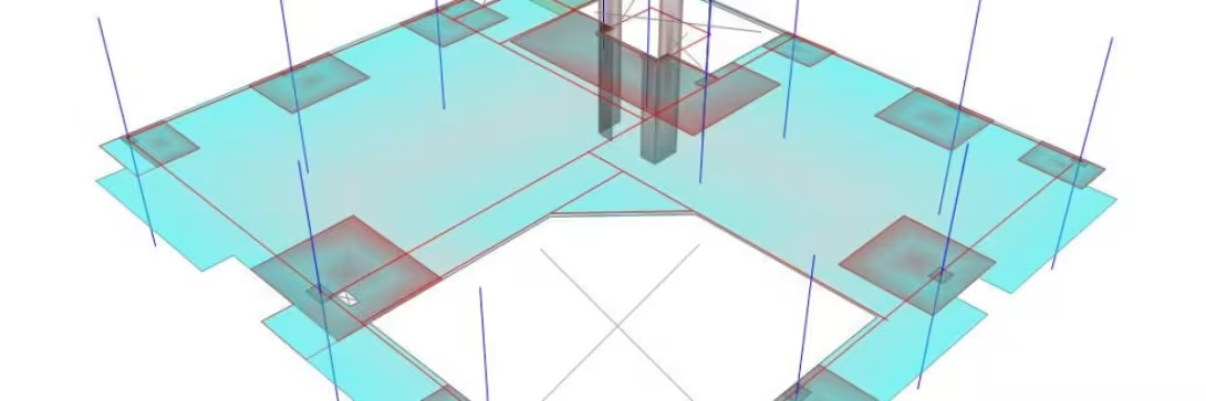
Crack Calculation and Verification in construction is an important process for ensuring the accuracy and safety of a structure. During construction, detecting and assessing cracks plays a crucial role in ensuring the stability and load-bearing capacity of structural elements.
In this article, LPC will guide you through crack calculation and verification according to TCVN 5574:2018 to help you understand the importance of crack calculation and verification in structural design.
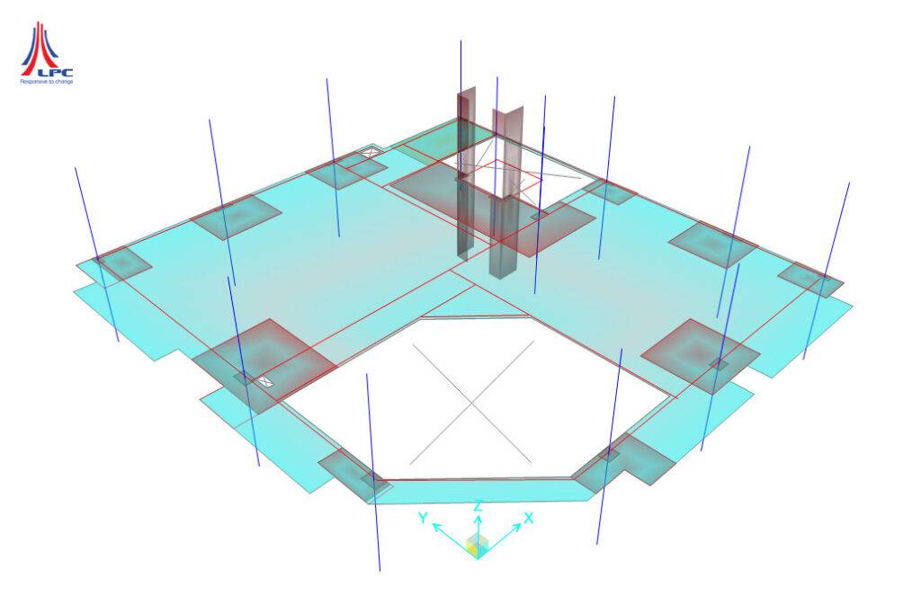
1. Input Parameters for Crack Calculation and Verification
When performing crack calculation and verification, the input parameters play an important role in enabling engineers to achieve the most accurate calculations. These include:
- Materials:
- Concrete:
- Strength grade B.
- Design axial compressive strength of concrete Rb.
- Design axial compressive strength of concrete for the second limit state Rb,ser.
- Design axial tensile strength of concrete for the second limit state Rbt,ser.
- Modulus of elasticity of concrete: Eb
- Reinforcement:
- Steel grade: CB300-V, CB400-V…
- Design tensile strength of reinforcement Rs.
- Design compressive strength of reinforcement Rsc.
- Modulus of elasticity of concrete: Es
- Concrete:
- Cross-sectional dimensions:
- Rectangular cross-section b * h
- Concrete cover thickness in the tension zone a, compression zone a’ (to the centroid of the reinforcement).
- Effective depth of the cross-section: ho=h-a
- Reinforcement diameter: ds
- Area of reinforcement in the tension zone: As
- Area of reinforcement in the compression zone: A’s
- Coefficient for converting reinforcement to concrete: α=Es/Eb
- Reinforcement ratio: μs=As/bho ; μ’s=A’s/bho
- Internal forces:
- Moment due to permanent and temporary loads (long-term and short-term): Mnh
- Moment due to permanent and long-term temporary loads: Mdh
2. Crack Calculation and Verification
2.1. Crack Resistance Verification of Reinforced Concrete Members
- Condition (1): M ≤ Mcrc
- M : Bending moment due to external forces about an axis perpendicular to the plane of action of the bending moment. (M=Mnh)
- Mcrc : Bending moment resisted by the cross-section when a crack forms (crack resistance of the member)
- If condition (1) is satisfied => the member does not crack; otherwise, crack calculation and verification of the crack width are required.
-
: Plastic bending resistance moment with respect to the tension fiber
-
: Elastic bending resistance moment of the transformed section with respect to the tension zone.
-
: Moment of inertia of the transformed cross-section of the member about its centroid.
-
- I, Is, I’s: Moments of inertia of the concrete section, tension reinforcement section, and compression reinforcement section, respectively.
- yt: Distance from the most highly tensioned concrete fiber to the centroid of the transformed cross-section of the member.
-
: Area of the transformed cross-section of the member.
-
- A, As, A’s : Cross-sectional areas of concrete, tension reinforcement, and compression reinforcement, respectively.
- : First moment of area of the transformed cross-section of the member about the most highly tensioned concrete fiber.
2.2. Calculation of Crack Width Perpendicular to the Longitudinal Axis of the Member
- Crack width perpendicular acrc,i is determined by the following formula:
- : Crack width due to long-term effects of permanent loads and long-term temporary loads.
- : Crack width due to short-term effects of permanent loads and temporary loads.
- : Crack width due to short-term effects of permanent loads and long-term temporary loads.
- φ1 : Coefficient accounting for the duration of load application, taken as:
- 1.0 : For short-term load application.
- 1.4 : For long-term load application.
- φ2 : Coefficient accounting for the surface shape of longitudinal reinforcement, taken as:
- 0.5 : For ribbed reinforcement and tendons.
- 0.8 : For smooth reinforcement.
- φ3 : Coefficient accounting for the loading characteristics, taken as:
- 1.0 : For members subjected to bending and eccentric compression.
- 1.2 : For tension members.
- σs : Stress in the tension reinforcement of a flexural member
- yc : Height of the compression zone of the transformed cross-section
- αs1, αs2 : Coefficients for converting reinforcement to concrete. 8.2.3.3.8
- : Transformed deformation modulus of compressed concrete.
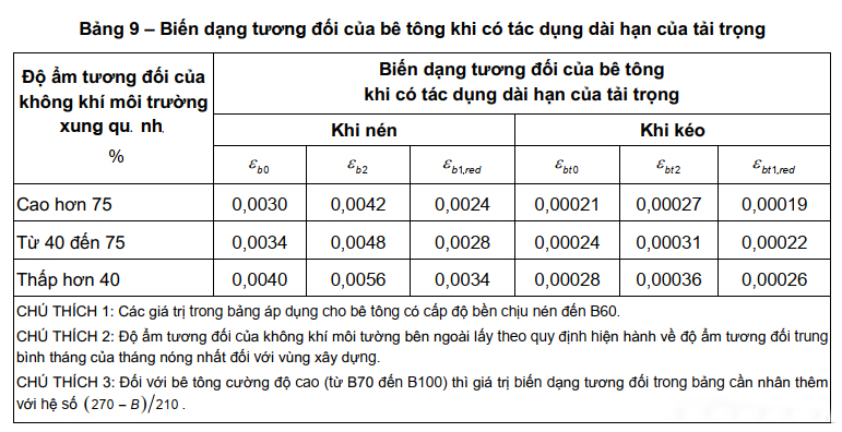
- εb1,red : Relative strain of concrete.
- For short-term load application:
- For normal-weight concrete, take: 0.0015
- For lightweight concrete, take: 0.0022
- For long-term load application:
- For normal-weight concrete: take according to Table 9
- For short-term load application:
- I,red : Moment of inertia of the compression zone of the transformed concrete cross-section.
- : Moments of inertia of the cross-sectional areas of the compressed concrete, của tension reinforcementand of compression reinforcement about the centroid of the transformed cross-section, excluding the concrete in the tension zone.

- : Basic spacing between adjacent cracks perpendicular to the member axis, Ls taken as not less than 10ds and 100 mm, and not greater than 40ds and 400 mm.

- : Area of the tension concrete cross-section, determined based on the height of the concrete tension zone xt. In all cases: 2a ≤
 ≤ 0.5h
 - : Area of the tension reinforcement cross-section.
- : Nominal diameter of reinforcement.
2.3. Crack Width Verification
Evaluating crack width during crack verification allows engineers to determine the extent of damage to the material and the structure surrounding the crack. This is important to ensure that the crack does not exceed the acceptable limit or significantly affect the structural integrity of the project.
- Verification condition:

- : Crack width caused by external forces.
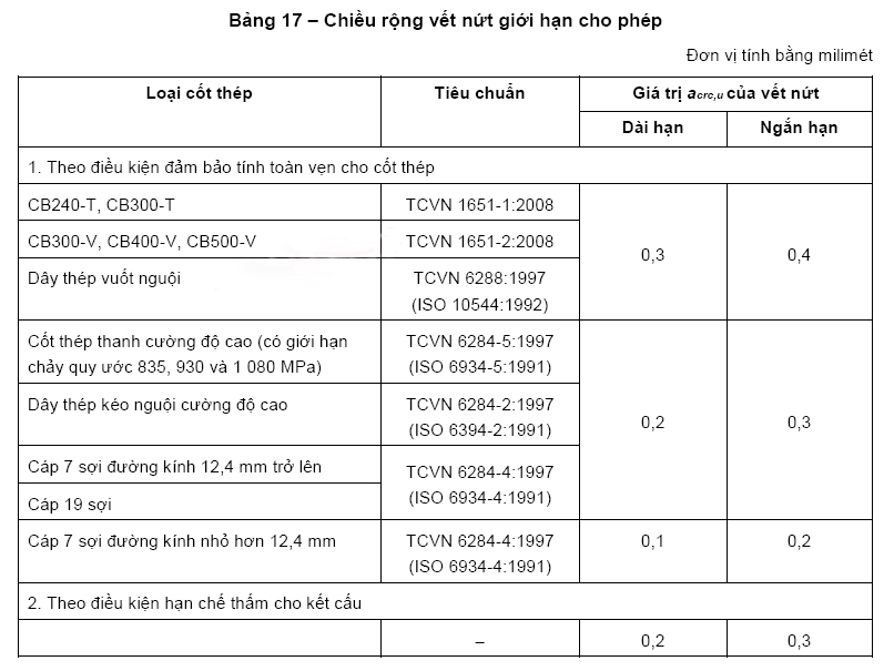
- : Allowable crack width limit, Table 17
- Check the width of short-term cracks do permanent loads and temporary loads:
![{ a }_{ crc }^{ nh }\quad \le \quad \left[ { a }_{ crc }^{ nh } \right]](https://ketcaupro.com/wp-content/ql-cache/quicklatex.com-9312d363adf051182a31e75e79ce7b02_l3.svg "Rendered by QuickLaTeX.com")
 : Short-term crack width:
![\left[ { a }_{ crc }^{ nh } \right]](https://ketcaupro.com/wp-content/ql-cache/quicklatex.com-a60b4bee88f18753c151b9d0f0f6cc4d_l3.svg) : Allowable short-term crack width limit, Table 17.
: Allowable short-term crack width limit, Table 17.- Check the width of long-term cracks do permanent loads and long-term temporary loads:
![{ a }_{ crc }^{ dh }\quad \le \quad \left[ { a }_{ crc }^{ dh } \right]](https://ketcaupro.com/wp-content/ql-cache/quicklatex.com-c7ff3625a34de7d89754dd0efe417783_l3.svg "Rendered by QuickLaTeX.com")
 : Long-term crack width:
![\left[ { a }_{ crc }^{ dh } \right]](https://ketcaupro.com/wp-content/ql-cache/quicklatex.com-5010871143253e219894e9640bd5a11d_l3.svg) : Allowable long-term crack width limit, Table 17.
: Allowable long-term crack width limit, Table 17.
The crack calculation and verification process is carried out in several steps to ensure the structural integrity of the project. In addition to crack calculation and verification, engineers must also perform other structural calculations. See you again in the next article with more technical content.
—- Lam Pham Construction Co., Ltd. – LPC
Hotline: 0911.29.9696
Website: https://lpc.vn
Facebook: Lam Pham Construction
Youtube: Lam Pham Construction
Tiktok: Lam Pham Construction
More articles
All news

Have a project in mind?
LPC engineers are ready to share their experience and propose the right solution for your project.